
Fisher Philharmonic
1937-1942
10
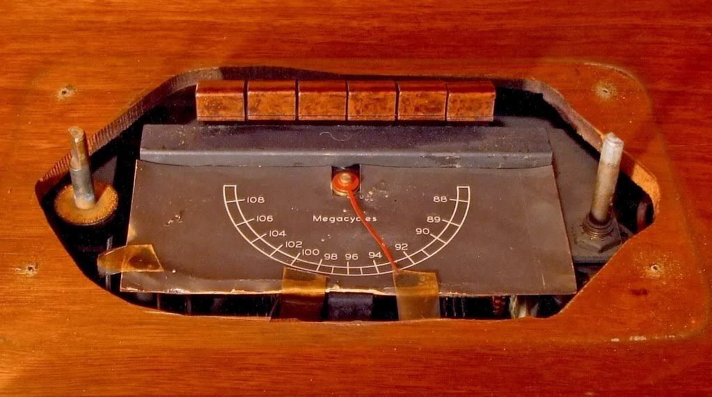
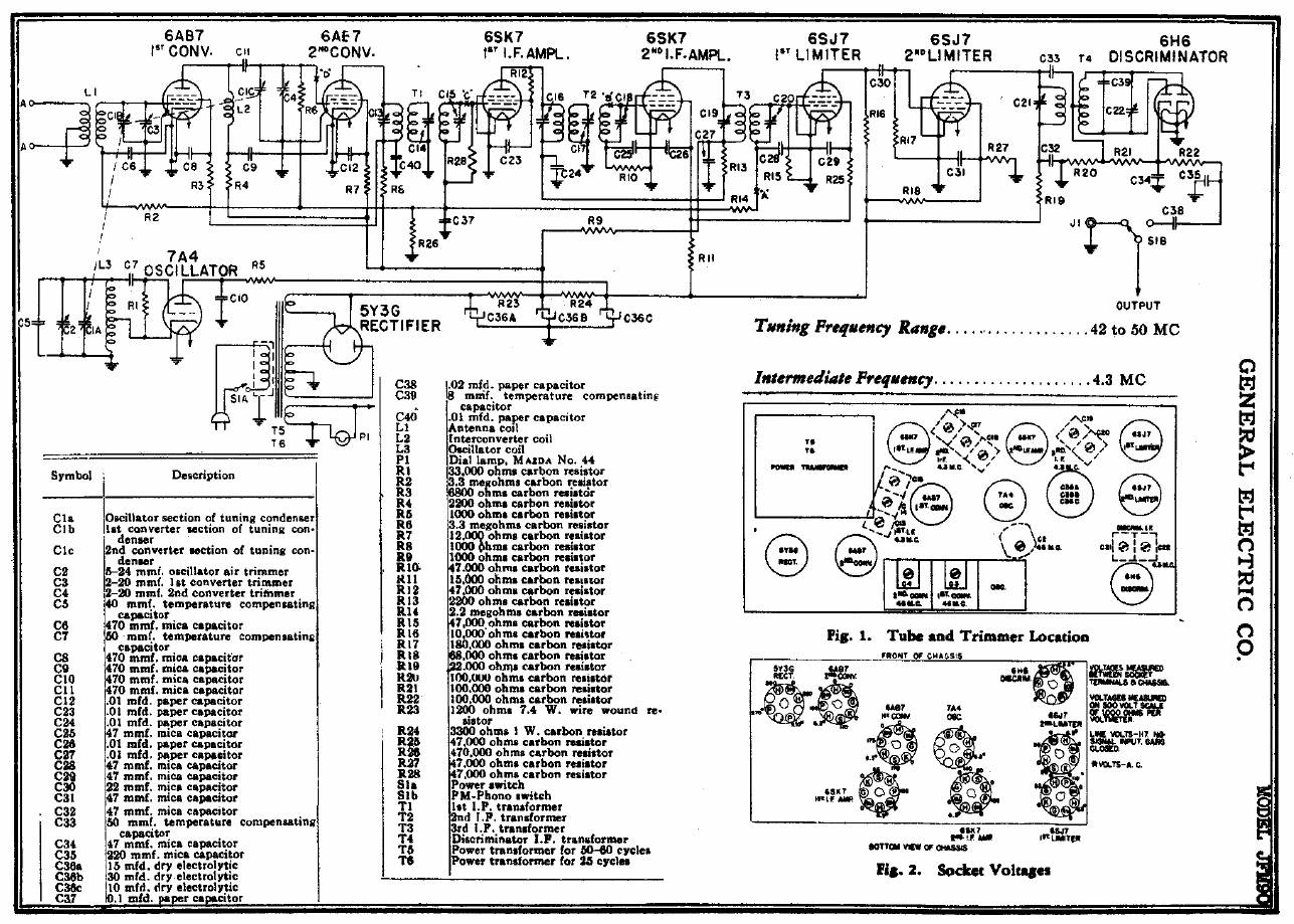
Sintonizador de FM
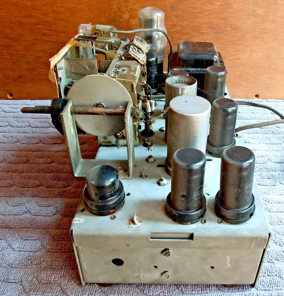
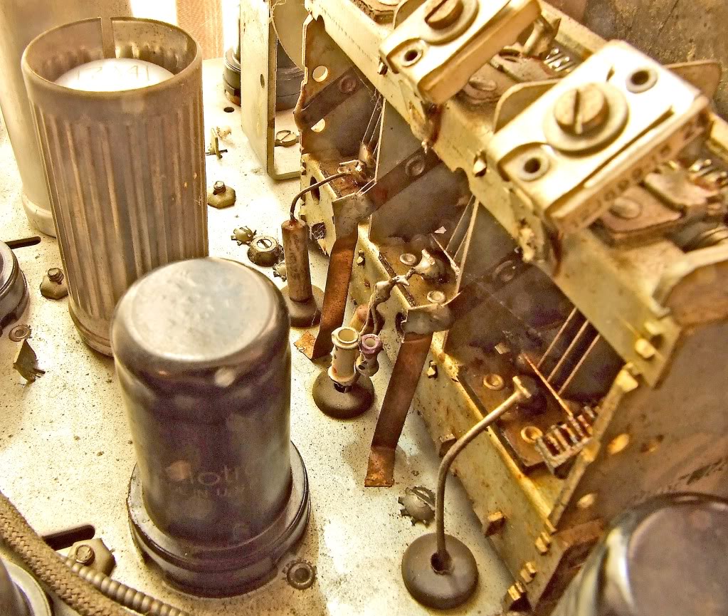
O sintonizador de FM utilizado no Philharmonic Futura K1 é um GE JFM-90! Ao verificarmos o mesmo observamos que provavelmente seria um excedente da fábrica que não seria mais comercializado. Nesta época o sistema de transmissão de FM estava migrando da banda de 42-50MHz para os 88-108MHz, e os sintonizadores ficaram subitamente obsoletos. A Philharmonic os comprou e os readaptou através da substituição das bobinas osciladora e de antena tornando-os aptos para nova banda. O dial original foi recoberto por uma placa de cartão impresso com a nova calibração. O Circuito original não recebeu alterações. As válvulas utilizadas são as mesmas do JFM-90 1) 5Y3, (2)6AB7, (2)6SK7, (2)6SJ7, (1) 7A4 e (1) pequenina 6H6. The dial scale is a piece of cardboard glued AND scotch-taped over the original.
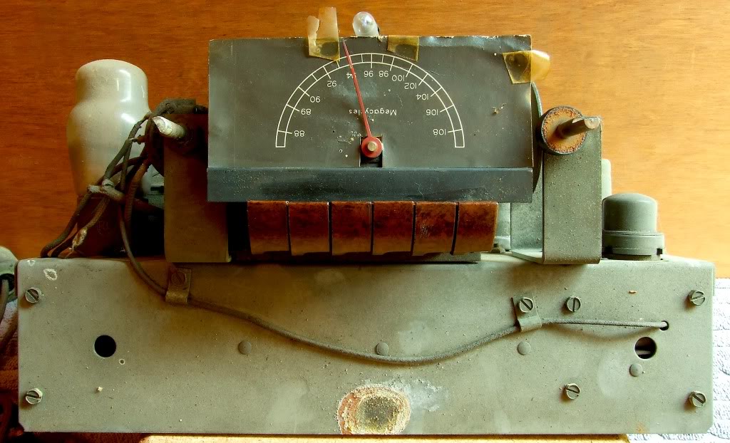
Outra peculiaridade intrigante foi a montagem do chassis em
ponta-cabeça com a inversão dos botões de seleção rápida das estações operando
de forma inversa. A montagem é certamente original pois esta é comprovada na
imagem apresentada no Consummer Report no segmento 7 desta análise.
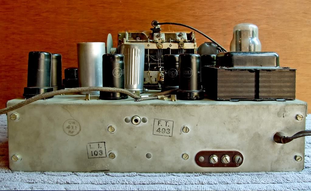
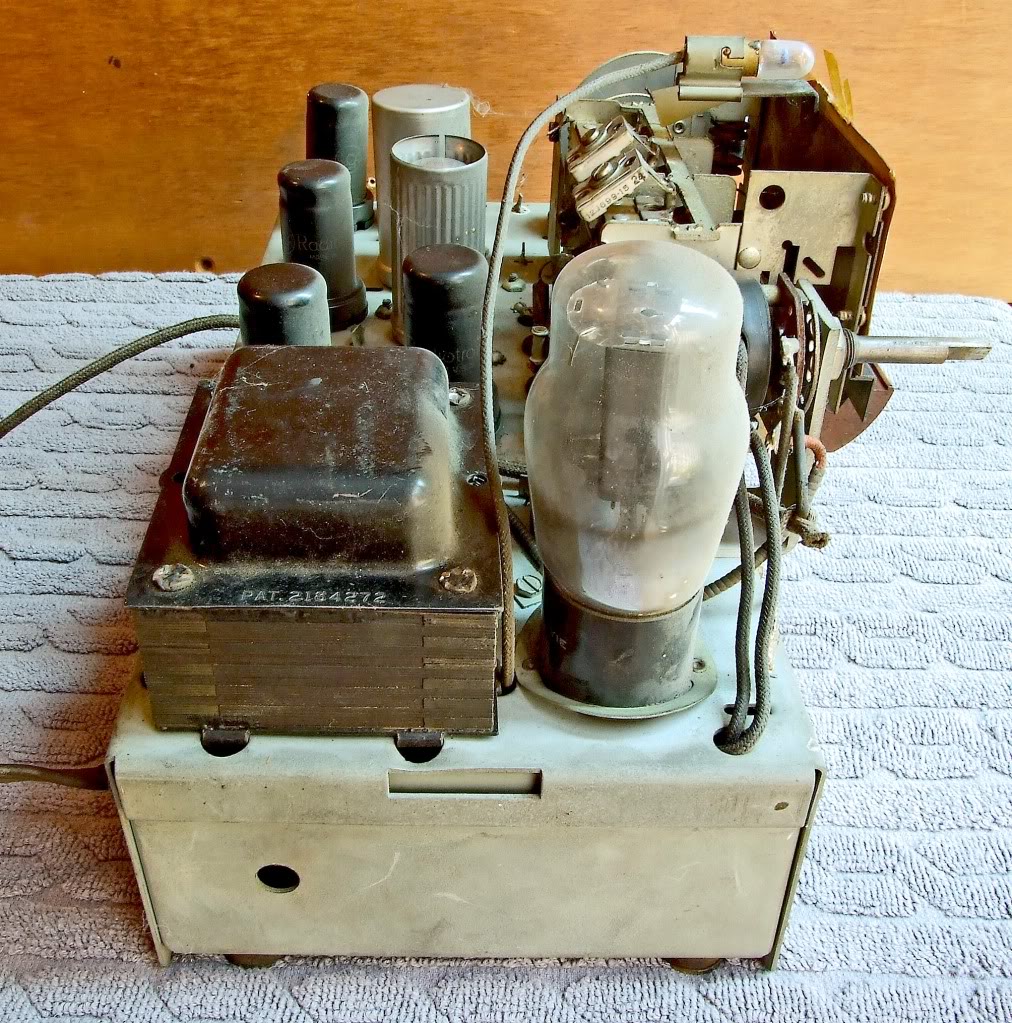
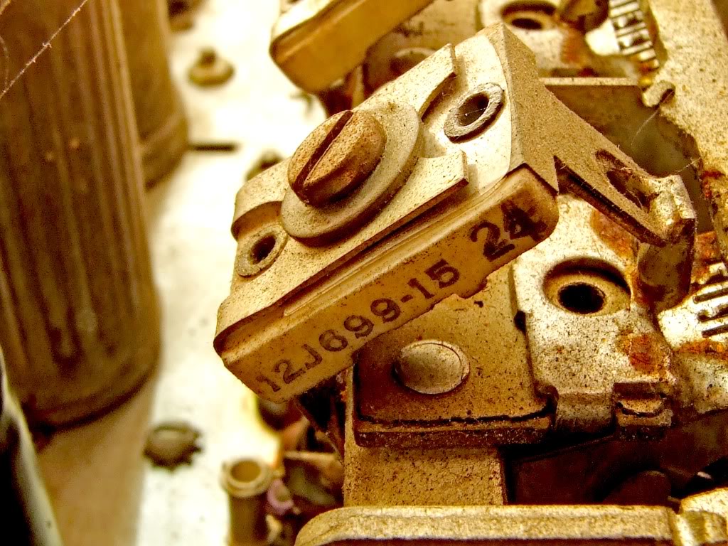
No chassis a marca GE e a patente gravada no transformador de
força.
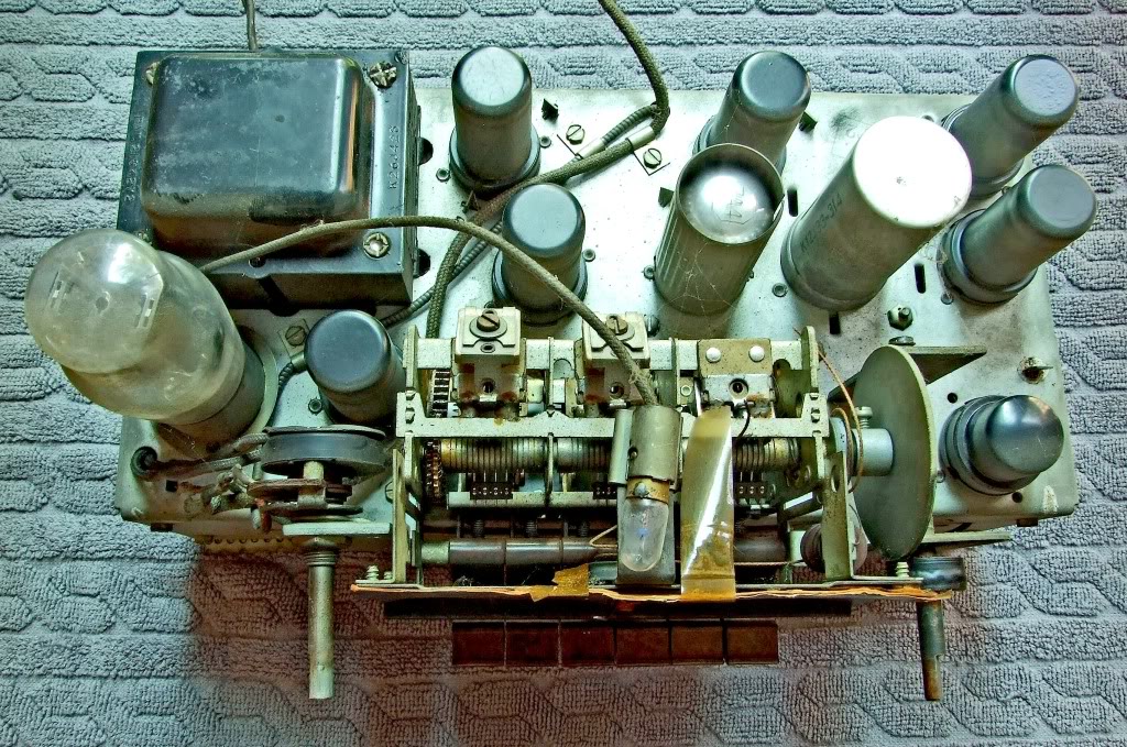
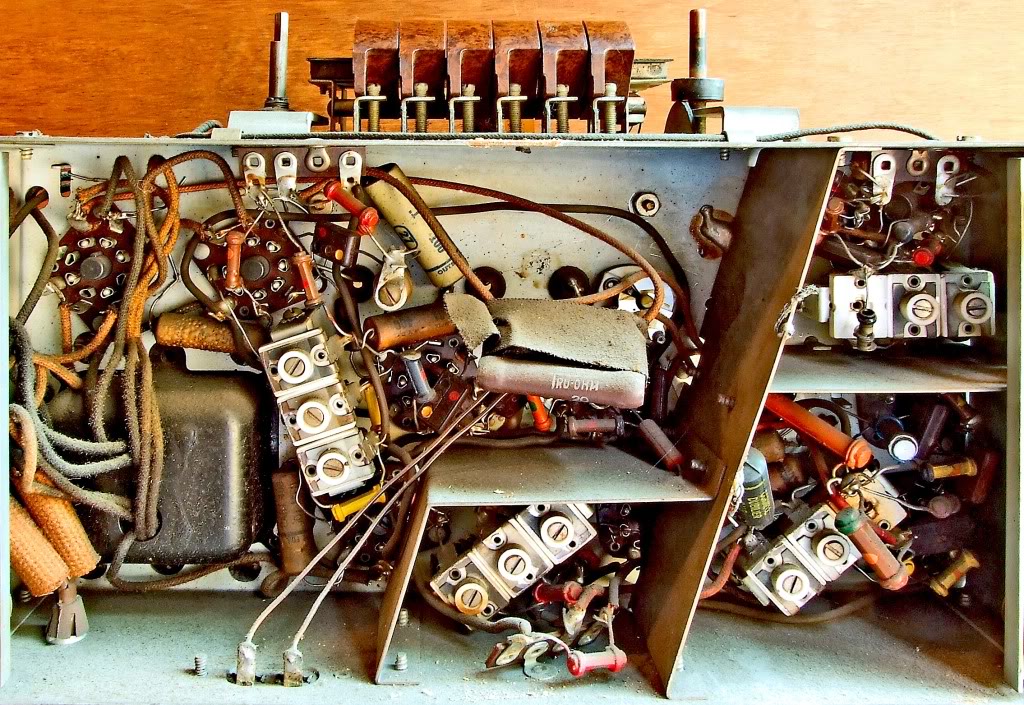
Capacitor de sintonia multi seções incorporando os trimmers de ajuste de
rotação.
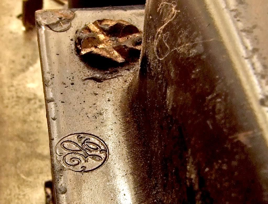
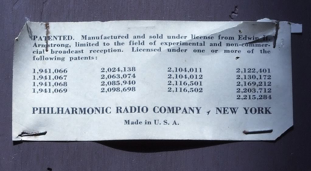
No gabinete a licença de Edwin Armstrong e a comprovação da
remanufatura pela Philarmonic Radio Company.
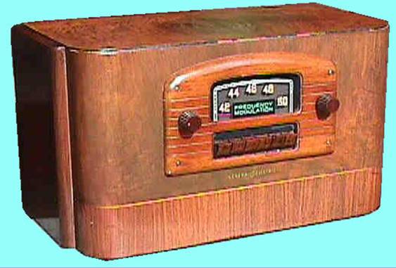
Tuner da GE JFM 90 como originalmente fornecido.
Construção do gabinete dos falantes e detalhes dimensionais.

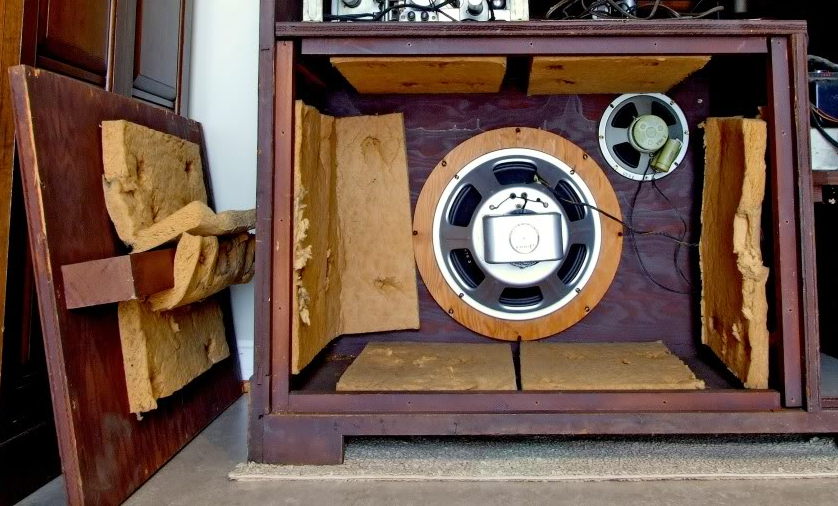
Vista interior do gabinete
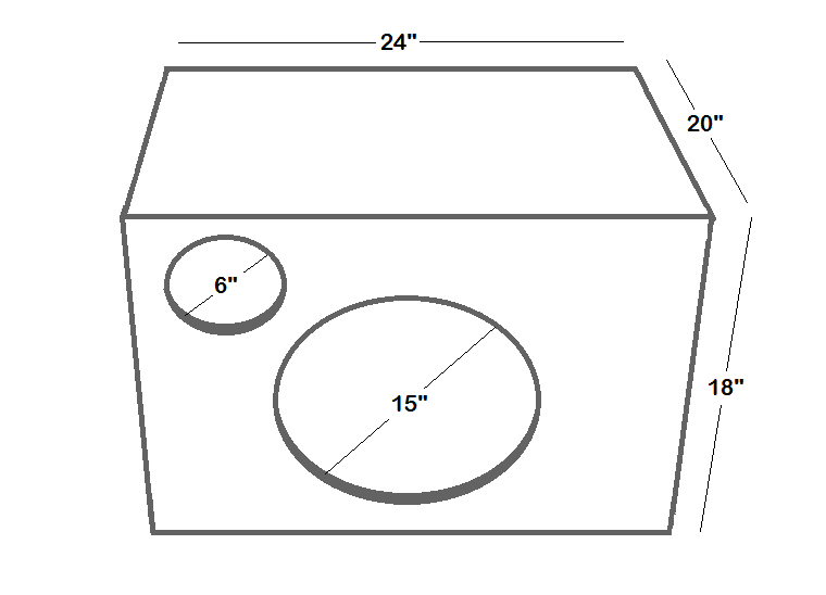
Dimensões do gabinete em polegadas. Caixa hermeticamente fechada.

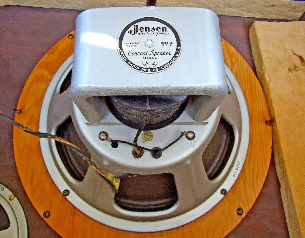
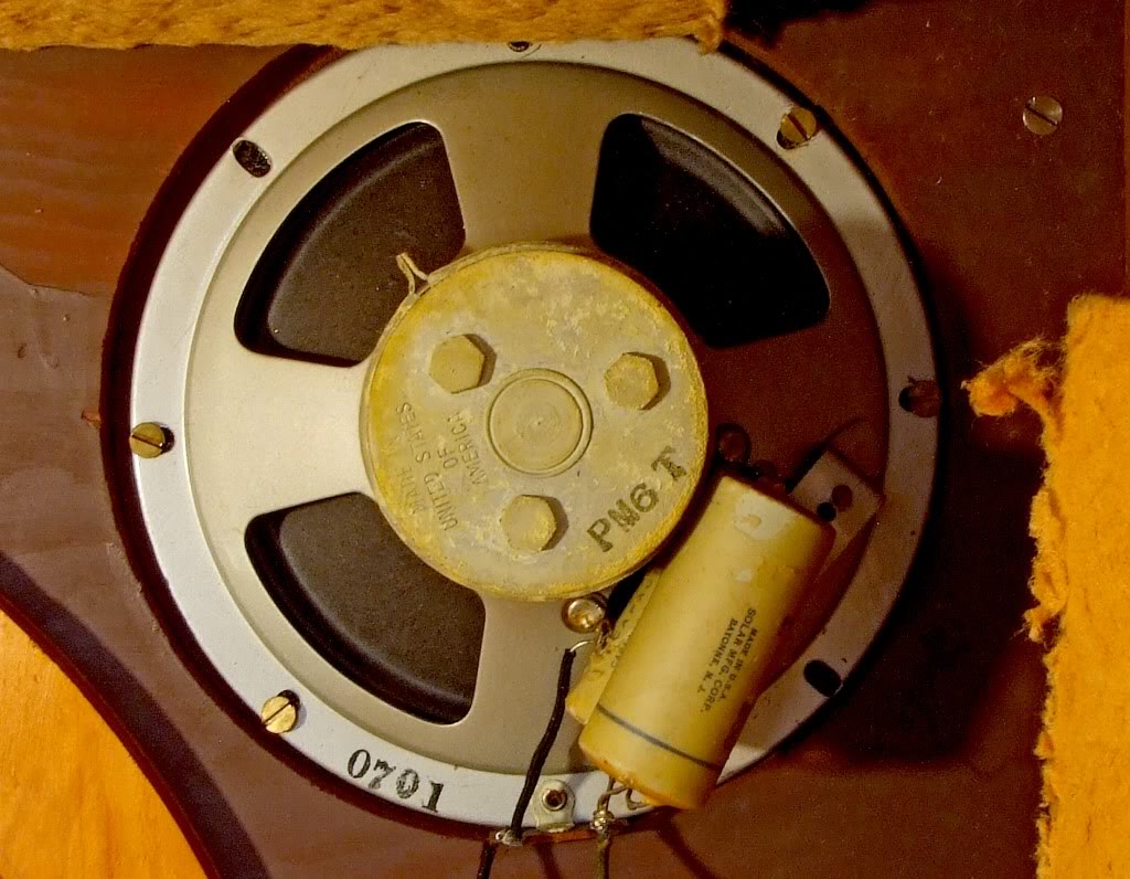
Ligações dos falantes. O gabinete é o mesmo para falantes de 12” ou 15”.
O anel de adaptação permite o uso do falante de 12” no mesmo gabinete.
Nos anos pós guerra a Philarmonic foi renomeada Fisher Radio Co. Outros itens interessantes poderão ser vistos em nosso segmento sobre Expansores e pré-amplificadores da General Electric.
xxxxxxxxxxxxxxxxxxxxxx
![]()
![]()